GNSS vehicle navigation solution based on ST AEK-COM-GNSST31 and core module Teseo-LIV3F
1. Introduction to AEK-COM-GNSST31
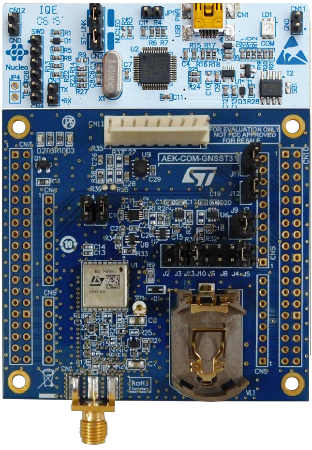
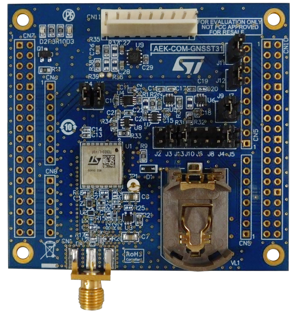
AEK-COM-GNSST31 is an evaluation board based on the Teseo-LIV3F GNSS module, based on the certified Teseo-LIV3F Global Navigation Satellite System (GNSS) module, which embeds the TeseoIII monolithic independent positioning receiver IC. Small, cheap and easy to develop are the characteristics of this product. The evaluation board is used with the X-CUBE-GNSS1 firmware to provide the necessary acquisition, tracking, navigation and data output functions without external memory support. MCUs developed for automotive applications can also be easily interfaced with SPC5 as part of the AutoDevKit™ program.
2. Core module Teseo-LIV3F
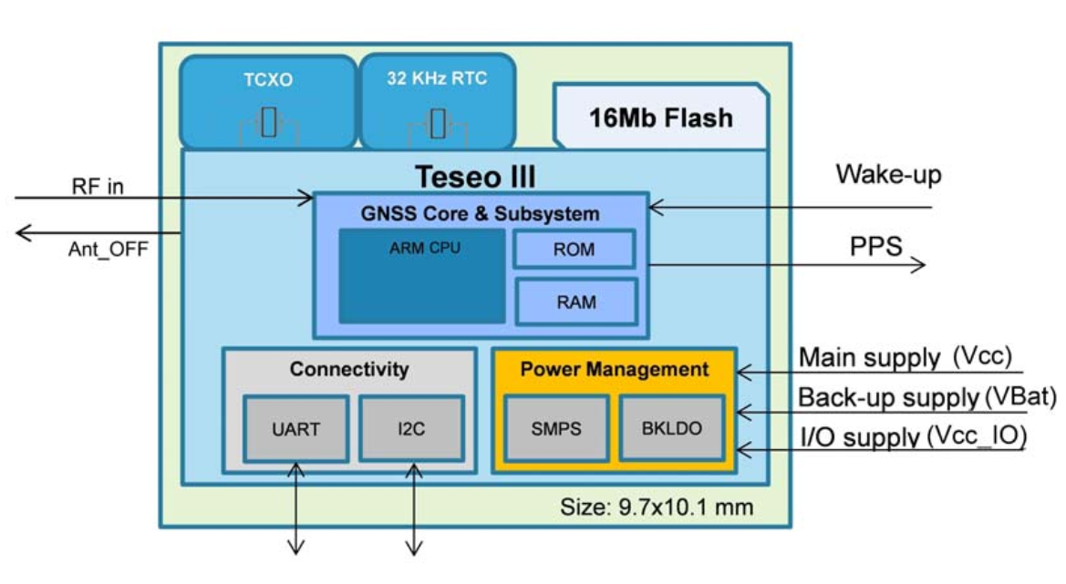
The core of AEK-COM-GNSST31 is Teseo-LIV3F. The Teseo-LIV3F module is an easy-to-use global module satellite navigation system (GNSS) independent module embedded in Teseo III single mode, in addition to the necessary power supply, RF and antenna ANT management , it communicates with the main control MCU using I2C or UART interface. Both interfaces support the GNSS NMEA protocol.
The X-CUBE-GNSS1 firmware runs on STM32 and includes drivers for the Teseo-LIV3F Global Navigation Satellite System (GNSS) device, middleware for NMEA protocol support and FreeRTOS for task scheduling to ensure better Asynchronous message parsing, the software comes with a sample implementation of the driver running on the AEK-COM-GNSST3 expansion board when connected to the NUCLEO-F401RE, NUCLEO-L476RG, or NUCLEO-L073RZ board.
3. Implementation of vehicle GNSS navigation
This solution is based on the AEK-COM-GNSST31 and NUCLEO-F401RE development boards to realize information exchange between the main MCU and the GNSS module through I2C under the standard NMEA protocol.
The I2C positioning sensor is a platform solution that implements Teseo-LIV3F standard firmware.
3.1 Hardware preparation
AEK-COM-GNSST31 Evaluation Board
NUCLEO-F401RE development board
USB-microUSB data cable for evaluation board and PC connection
3.2 Software preparation
TESEO-SUITE
STM32CUBE-MX
Atollic-TRUE Studio
3.3 Configure Teseo-LIV3F through TESEO SUITE PC tool
① Connect AEK-COM-GNSST31 to the top of NUCLEO-F401RE via morpho as shown
Install STM32 firmware
Select Tool->X-NUCLEO-GNSS1A1
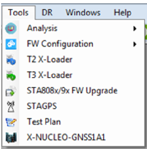
The X-NUCLEO-GNSS1A1 panel appears
Click Update my STM32-NUCLEO board for X-NUCLEO-GNSS
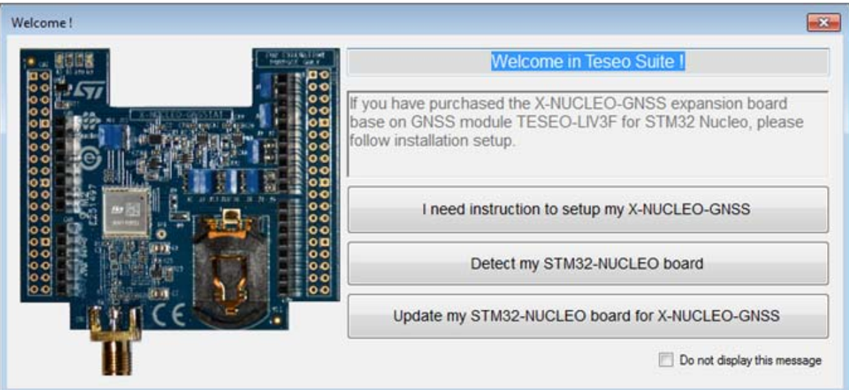
The STM32 X-Nucleo-GNSS panel display
Select the firmware
STM32_Nucleo64-F401RE_UARTBridde.bin
Push the Upload button
②Open TESEO-SUITE PC Tool, enable UART/COM connection against the NUCLEO-F401RE, and use the NMEA decoding panel on TESEO-SUITE to send the following commands
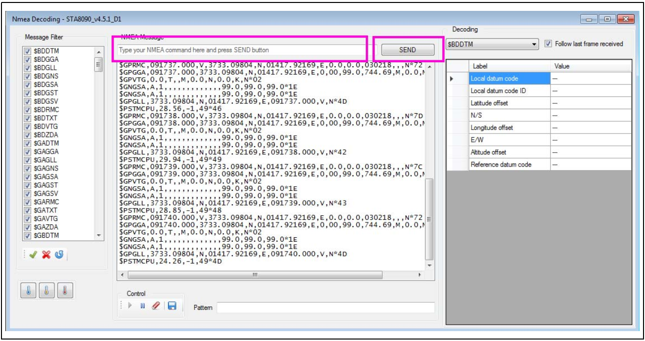
$PSTMCFGMSGL,3,1,0,0
$PSTMSETPAR,1227,1,2
$PSTMSAVEPAR
These commands will: clear the I2C message list, turn off eco-ing information and save the configuration in flash
3.4 Configure NUCLEO-F401RE I2C
Configure the I2C peripheral function in STM32CUBEMX as shown below and generate the project
Enable the I2C-1 bus on NUCLEO-F401RE
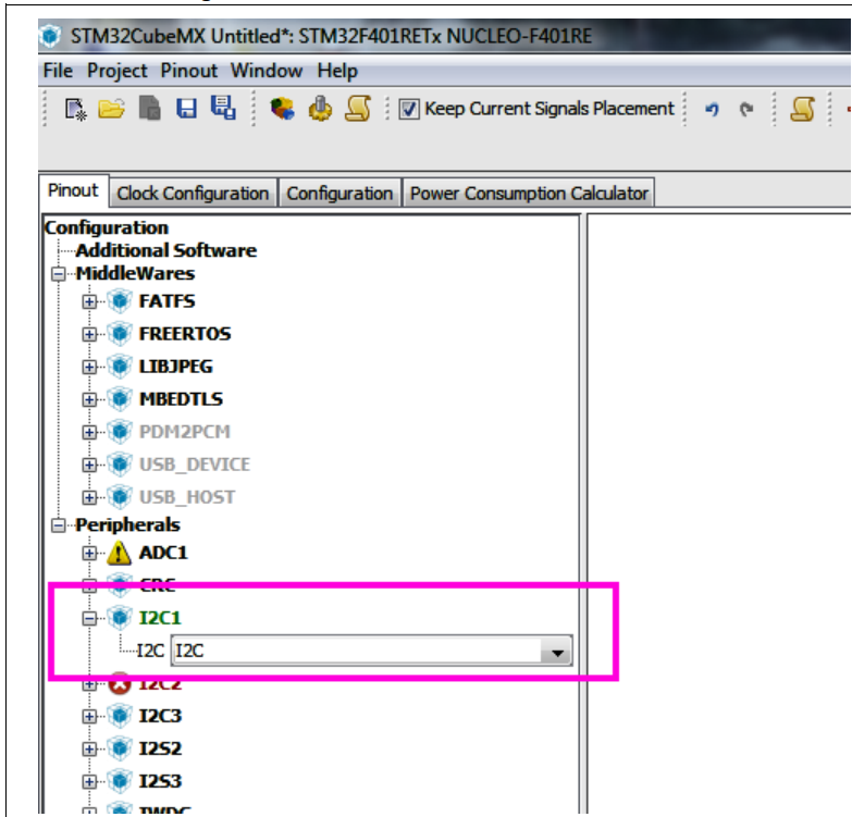
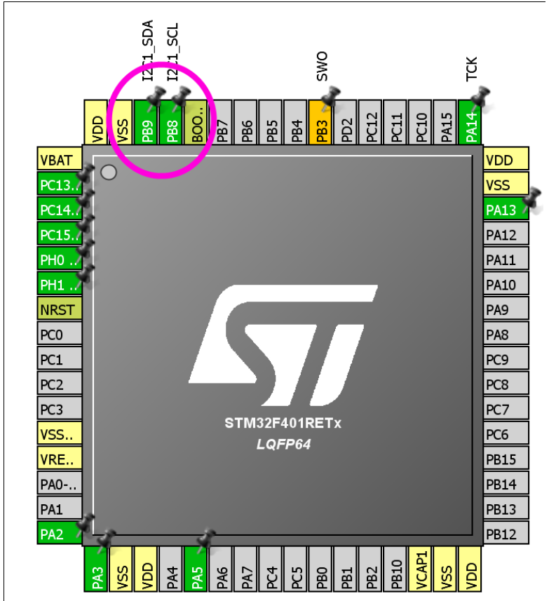
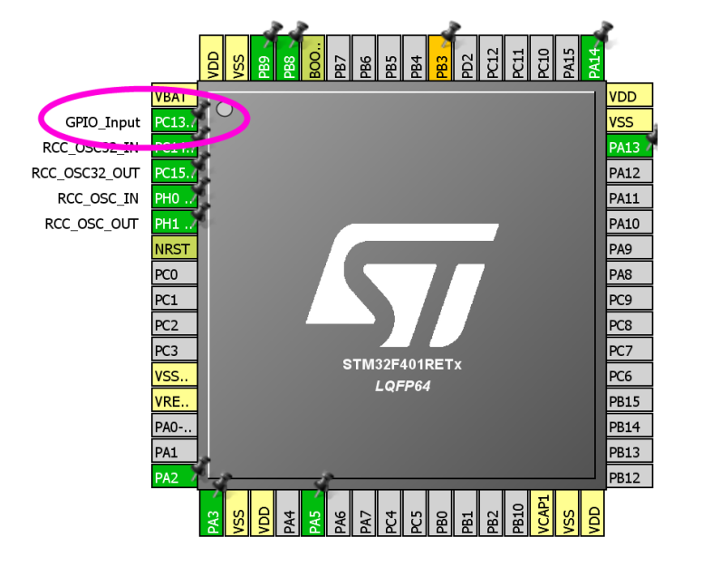
Configure the Blue-Button as GPIO_EXTI13
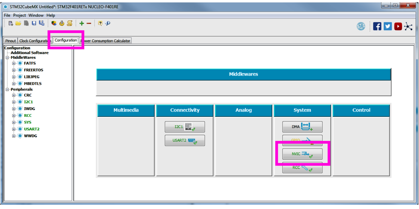
In the configuration TAB press the NVIC button to configure the NVIC
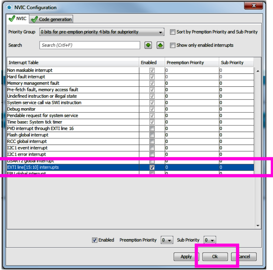
Enable the Blue-Button (EXTI-interrupts) and confirm the configuration pressing the OK button
Enable the USART-2 to enable communication between STM32 and the Terminal-Console running on PC
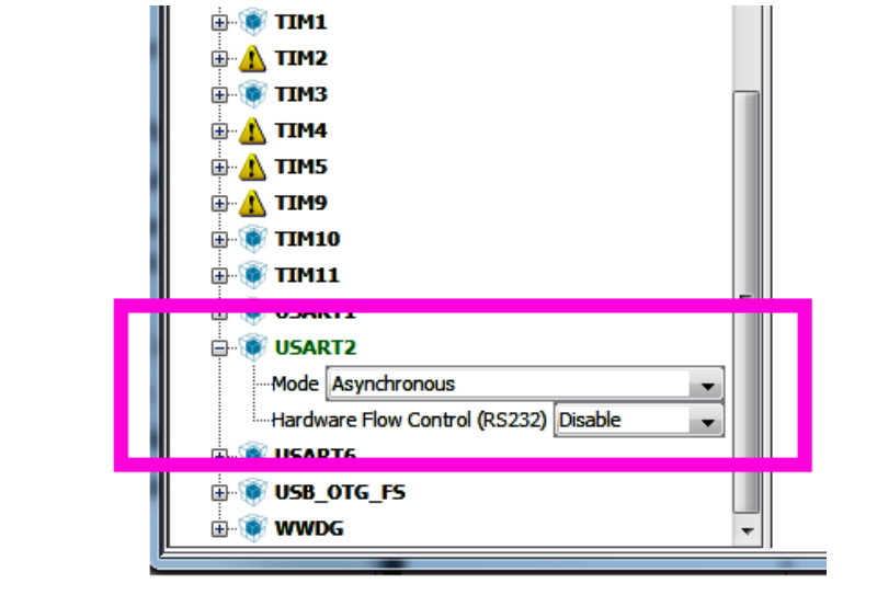
Configure the USART-2
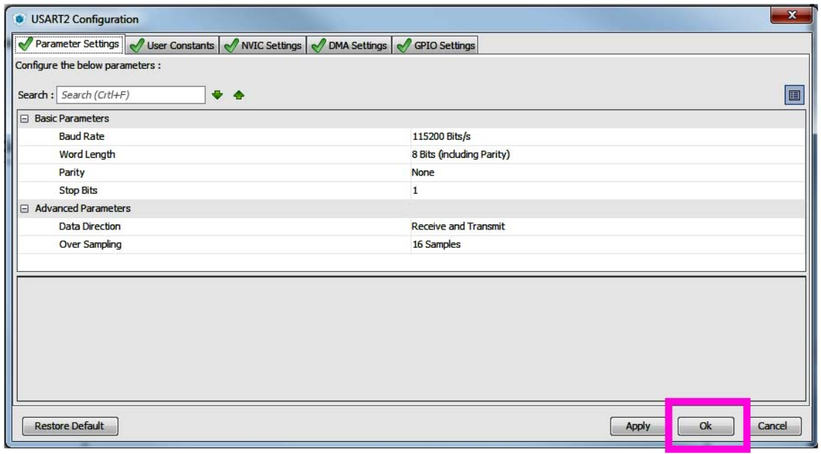
Configuration is complete and C code is generated
3.5 Software implementation
Through the above configuration of STM32Cube-MX, the C code for the required architecture is generated including:
I2C bus, UART and PC communication and blue button as interrupt button function
Add the following code to make the PC display printing information
void Console_Write(uint8_t *string){
HAL_UART_Transmit(&huart2, string, strlen((char *)string), 1000);
}
Add blue button callback function function
static volatile _read = 0;
void HAL_GPIO_EXTI_Callback(uint16_t GPIO_Pin){
_read = 1;
}
Define NMEA command related variables
static const char *gpgll_msg = "$PSTMNMEAREQUEST,100000,0\n\r";Main function code
while (1) {
    HAL_I2C_DeInit( & hi2c1);
    HAL_I2C_Init( & hi2c1);
    AN5203 Rev 2 17 / 23
    AN5203 Finalize the C - Code in the project
    twenty two
    if (_read == 1) {
        _read = 0;
        Console_Write("Sending commands...");
        HAL_I2C_Master_Transmit( & hi2c1, 0x3A << 1, (uint8_t *
        ) gpgll_msg, strlen(gpgll_msg), 2000);
        Console_Write(" got:... \r\n");
        for (read_buf[180 - 1] = 0; read_buf[180 - 1] != 0xff;) {
            HAL_I2C_Master_Receive( & hi2c1, 0x3A << 1, read_buf, 180,
                2000);
            for (i = 0; i < 180; ++i)
                if (read_buf[i] != 0xff)
                    HAL_UART_Transmit( & huart2, & read_buf[i], 1, 1000);
        }
        Console_Write("\r\n");
    }
}
Where in detail:
1. in line-4 the application waits the Blue-button event happens.
2. In line-7 the main-processor send to the Teseo-LIV3F on I2C-bus the $PSTMNMEAREQUEST command to request a $GPGLL message
3. In line-10 the main processor read the data sent by Teseo-LIV3F on I2C-bus
4. In lines 11-13 the received data are sent on the PC-Terminal console
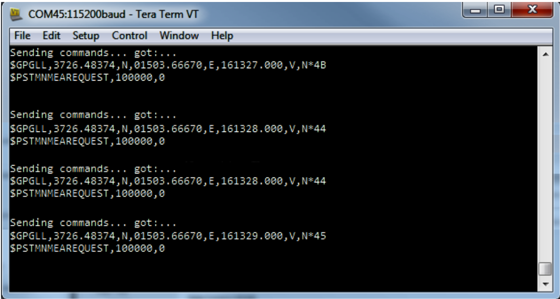
Demonstrate the results on the terminal
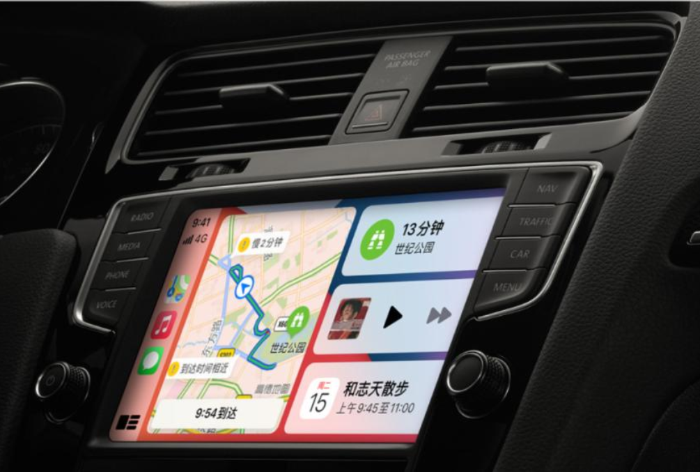
Scenario application diagram
Display board photo
Solution block diagram

Core technology advantages
Teseo-LIV3F module is an easy-to-use global module satellite navigation system (GNSS) independent module that supports multi-satellite positioning. The independent positioning receiver integrated circuit can work in multiple positioning systems simultaneously: Galileo/GPS/Glonass/Beidou/QZSS) . Supports standard GNSS NMEA protocol.
Project specifications
Sensitivity:- 162dbm indoor (tracking mode)
Interface: UART and I²C port
Configurable digital I/O time pulse
Wake-up input
NMEA protocol
Advanced GNSS:
Autonomous prediction
Server-based prediction
Server-based real-time
Compatible with SPC5 PowerPC
LNA and SAW filters on the RF path
SMA female antenna connector
Equipped with battery holder
Highly compact design: 70 x 65 mm
Working power supply voltage: 3.3 - 5v
Ambient temperature:-40/+85°C
Part of the AutoDevKit™ program
Comply with RoHS and WEEE standards

