Door Control System Design for Automotive Electronics
By 2030, electronics will account for 50% of a car’s cost, and one of the growth areas for electronics is the doors. Door electronics design is a challenge; each door requires a controller, a controller area network (CAN), or a local interconnect network (LIN) transceiver to connect to the rest of the vehicle systems, as well as multiple motor drivers and voltage regulators. These devices and networks can become complex, expensive, bulky, and time-consuming to design in, so designers are looking for ways to simplify the application and bill of materials (BOM).
Application-specific standard products (ASSP) can be designed specifically for automotive applications to ease the designer’s workload. In addition, these solutions allow designers to take a centralized or decentralized approach to door electronics design, depending on the complexity and cost constraints of the design.
This article describes the evolution of connected door electronics and explains the pros and cons of both centralized and decentralized approaches. It then explores how ASSP can be used to simplify the design of a single body control unit (BCU) in a centralized design, or individual BCUs for each door in a decentralized design. This article will also discuss how these approaches can be integrated into the car’s In-Vehicle Network (IVN) through CAN and LIN solutions. We will use solutions from ON Semiconductor as an example.
The Evolution of Automotive Electronic Systems and Network Capabilities
As fuel injection began to replace carburetors in the 1970s, automotive electronic systems began to require an engine control unit (ECU) to manage fuel injection. Since then, electronic systems have proliferated rapidly. Today, premium cars have comprehensive electronic systems in four key areas:
Powertrain (engine control, transmission control, starter/alternator)
Body and comfort (lighting, air conditioning, seats and doors, remote keyless entry)
Safety (ABS, power steering, airbags, driver assistance)
Infotainment (navigation, audio, multimedia, cellular connectivity, Bluetooth, telematics, instrument cluster)
All of these systems use dedicated computing modules, which are linked by IVNs based on CAN and/or LIN technology.
CAN is a vehicle bus standard designed to allow computing modules and sensors/actuators to communicate without the need for a host computer. The standard prioritizes connections so that the most important devices are handled first to avoid contention issues when multiple devices are transmitting simultaneously, and to ensure that critical functions are not delayed. CAN is too expensive to connect every electronic component in a vehicle, so it is often paired with LIN to add all devices to the IVN. For non-time-critical functions, usually related to passenger comfort, LIN uses serial link technology with less complexity and cost.
This article focuses on the electronic systems associated with the doors. Like the rest of the car, doors are increasingly using electronics for the convenience of the driver.
Most modern cars have electronically controlled windows, door locks, and mirrors, with features such as pinch protection recently introduced. Luxury cars have exterior mirror defrost, mirror-mounted turn signals, and welcome lights. The next generation of high-end models will include electrochromic mirror control, which dims the side mirrors based on the brightness of other vehicles' lights.
Decentralized vs. Centralized Automotive Electronic Control
Centralized topologies for door electronics are the most common approach today, especially for low-cost cars with limited door functionality. The BCU is a module consisting of the INV system, microprocessor, actuator drivers, and discrete components that connect to the actuators in each door via live wires and separate CAN or LIN communications wiring. The main advantages of this approach are cost (only one BCU is required) and scalability (Figure 1).
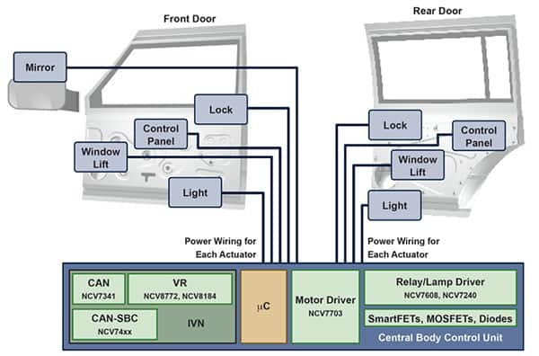
Figure 1: Centralized door electronics saves costs by using a single BCU. (Image source: ON Semiconductor)
However, centralized topologies are falling out of favor in premium vehicles because they require more functionality, which in turn requires more wiring. As a result, the wiring harnesses become bulky, complex, and expensive.
Another option is a decentralized approach, where each door has its own BCU. In this implementation, most of the wiring is local, with only one power supply required for the BCU (which then distributes it locally to the door actuators) and extends to the rest of the vehicle via CAN and/or LIN connections. The main advantages are that the weight, complexity, and cost of the wiring harness are greatly reduced, and the design flexibility of the BCU allows it to be adapted to the specific door. For example, the front door BCU requires additional functionality to assist with the exterior mirrors (Figure 2).
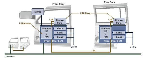
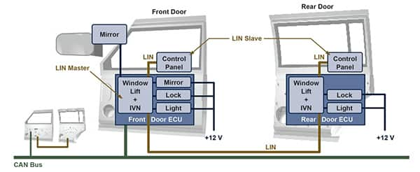
Figure 2: Decentralized systems reduce the weight and complexity of the wiring harness. (Image source: ON Semiconductor)
While decentralized topologies are becoming more popular, that doesn’t mean that centralized approaches are going away. The choice of design approach largely depends on the tradeoff between cost and wiring harness complexity.
Suppliers offer solutions that simplify the design of decentralized or centralized solutions. For example, ON Semiconductor offers a wide range of ASIC, ASSP, and discrete components for door electronics; designers are then free to choose their preferred microcontroller (Figure 3).
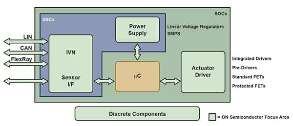
Figure 3: ON Semiconductor offers a range of ASIC, ASSP, and discrete solutions for both decentralized and centralized BCUs, giving designers the freedom to choose their preferred microcontroller. (Image source: ON Semiconductor)
In-Vehicle Networks
Whether designers choose a decentralized or centralized door electronics control system design, they need to ensure that the BCU is integrated into the IVN. CAN connectivity is simplified by pairing a CAN controller with a CAN transceiver, which forms the interface between the controller and the physical bus. One example of a CAN transceiver suitable for automotive applications is the ON Semiconductor NCV7341D21R2G. This is a CAN device that operates at speeds up to 1 Mbit/s. The chip features differential receivers with a high common-mode range to provide good electromagnetic immunity (EMI) in the harsh automotive environment. In addition, the chip’s bus pins are protected from voltage transients that could upset the automotive electrical system (Figure 4).

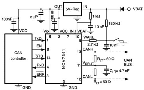
Figure 4: Typical application schematic of the NCV7341D21R2G CAN transceiver with a 5 V CAN controller. This transceiver is ideal for connecting to the IVN for both decentralized and centralized door systems. (Image source: ON Semiconductor)
Decentralized systems require not only CAN connectivity to the IVN, but also LIN connectivity between the front and rear BCUs, as shown in Figure 2. The front door BCUs are connected to CAN, but to save cost and wiring, the rear door BCUs are daisy-chained to the front door BCUs via LIN. LIN features a single-wire connection to each node, which simplifies wiring and reduces cost. Although throughput is limited to a maximum of 20 kb/s, this is sufficient to control devices such as door locks, windows, and exterior mirrors.
For LIN connectivity of door-mounted electronics, ON Semiconductor's NCV7321D12R2G LIN transceiver is an ideal choice. The chip contains a LIN transmitter, a LIN receiver, a power-on reset (POR) circuit, thermal shutdown, and four operating modes (unpowered, standby, normal, and sleep). These modes are determined by the supply voltage (VBB, 5 to 27 V), the input signals enable (EN) and WAKE, and activity on the LIN bus. The transceiver is optimized for maximum throughput and has good EMI characteristics due to the low slew rate of the LIN outputs.
The LIN topology uses a single master node to control a series of up to 16 slave nodes. In a decentralized system, the front and rear door BCUs comprise a master node, while peripherals such as window control panels comprise slave nodes, see Figure 2. The master node pairs a LIN transceiver with a suitable microcontroller (Figure 5).
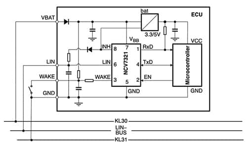
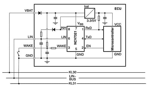
Figure 5: Typical application schematic for the NCV7321D12R2G LIN transceiver in a master node configuration. Each master node can control up to 16 slave nodes. (Image source: ON Semiconductor)
Door Actuator Drivers
For either a decentralized or centralized topology, the other key component of the BCU is the actuator driver. The driver is required to power the door locks, mirrors, windows, and other systems. ON Semiconductor offers a triple half-bridge driver, the NCV7703CD2R2G, that is specifically designed for these automotive and industrial motion control applications. The three half-bridge drivers are independently controlled via a standard serial peripheral interface (SPI) and provide a typical output of 500 mA and a maximum output of 1.1 A. The chip operates from a supply voltage of 3.15 to 5.25 V and a load voltage of 5.5 to 40 V.
A key design constraint is the maximum die temperature. The die temperature must not exceed 150°C, even though this limits how many of the device's three drivers can be used simultaneously.
Output drive control (and fault reporting) is handled via the SPI port. An EN function provides a low quiescent current sleep mode when the device is not in use, and pull-down resistors are provided on the EN, SI, and SCLK inputs to ensure that they default to a low power state when the input signals are interrupted.
Figure 6 shows how the NCV7703CD2R2G triple half-bridge driver can be used in an exterior mirror adjustment system. In this arrangement, the outputs from the three half-bridge drivers power two motors to move the mirrors in the X and Y directions.
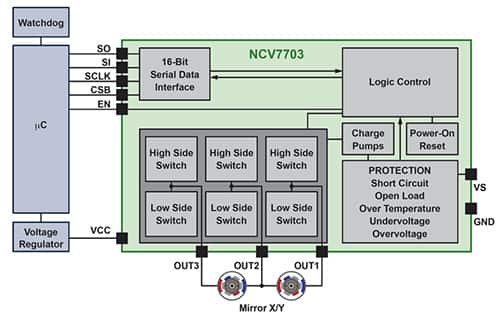
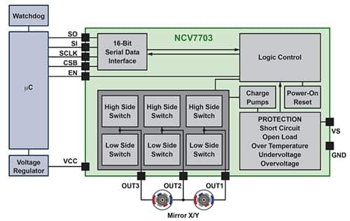
Figure 6: This block diagram shows the ON Semiconductor NCV7703CD2R2G triple half-bridge driver in an exterior mirror adjustment application, illustrating how the outputs from the three half-bridge drivers power two motors to move the mirrors in the X and Y directions. (Image source: ON Semiconductor)
A single microprocessor can be used to control multiple NCV7703CD2R2G triple half-bridge drivers, reducing the BOM of the door electronics system. The most effective way to achieve this is to operate the drivers in parallel with each device using multiplexed control.
In a serial configuration, the programming information for the last device in the serial string must first pass through all previous devices. The parallel control topology eliminates this requirement, but at the expense of narrowing the processor selection to devices with a chip select (CSB) pin corresponding to each driver. The serial data is then recognized only by the device activated through its respective CSB pin (Figure 7).
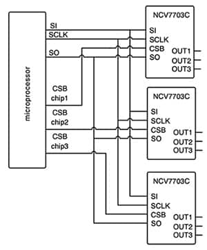
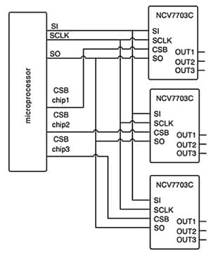
Figure 7: The BOM cost of the door electronics system can be reduced by using a single microprocessor to control multiple triple half-bridge drivers. (Image source: ON Semiconductor)
The NCV7703CD2R2G triple half-bridge driver requires 5 V regulation at the supply input for internal operation. ON Semiconductor’s NCV8518BPWR2G linear regulator is an ideal choice for this requirement. The chip features a fixed 5 V output that can be adjusted within a ±2% range. Suitable for all automotive environments, the device features a low typical dropout voltage of 425 mV and a low quiescent current of 100 µA. Safety features include thermal shutdown, short-circuit protection, and the ability to withstand transients up to 45 V. The linear regulator can also be used to power the BCU’s microprocessor (Figure 8).
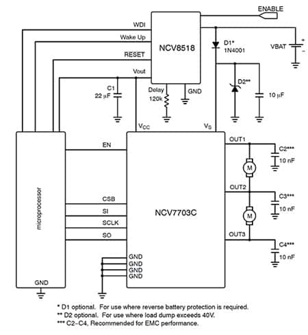
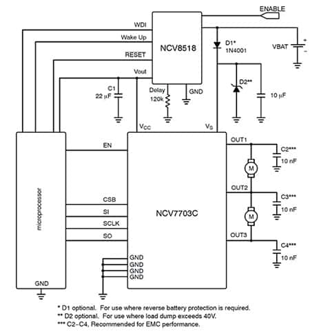
Figure 8: The NCV8518BPWR2G linear regulator is ideal for providing a 5 V output for the actuator drivers and microprocessor on the BCU. (Image source: ON Semiconductor)
Another linear regulator option for door electronics parts that require lower cost is the NCV8184DR2G. This chip provides an adjustable buffered output voltage between -3.0 and 45 V and closely follows the (±3.0 mV) reference input. The operating voltage is 4.0 to 42 V.
A useful feature of the NCV8184DR2G is that in a conventional configuration, it can withstand a short to the car battery without damage (Figure 9). The chip can also withstand a short to the battery when powered by a lower voltage isolated supply.
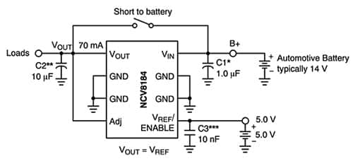
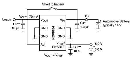
Figure 9: The NCV8184DR2G is a low-cost BCU voltage regulation option that can withstand a short to the car battery. (Image source: ON Semiconductor)
Discrete Components
In addition to monolithic devices for IVN, actuator drivers, and voltage regulation, ON Semiconductor offers a range of discrete components for door electronics, such as automotive-grade Zener diodes. These devices provide transient voltage suppression (TVS) to protect sensitive silicon components in the BCU from voltage spikes caused by external factors such as lightning strikes and electrostatic discharge (ESD). (For more information on protecting automotive electronic systems, see the Digi-Key library article "Design-in TVS diode protection improves CAN bus reliability.")
A second application for Zener diodes is in combination with resistors and MOSFETs to form the basis of inexpensive, compact linear regulators. Linear regulators can be assembled from discrete components to regulate the supply voltage from the car battery to power the actuator pre-drivers and drivers (Figure 10). The car battery provides about 14 V, while the supply voltage (VS) of the NCV7703CD2R2G triple half-bridge driver can be between 5.5 V and 40 V. This simple and inexpensive Zener diode linear regulator maintains a stable voltage for the door electronics as the voltage output from the car battery changes.
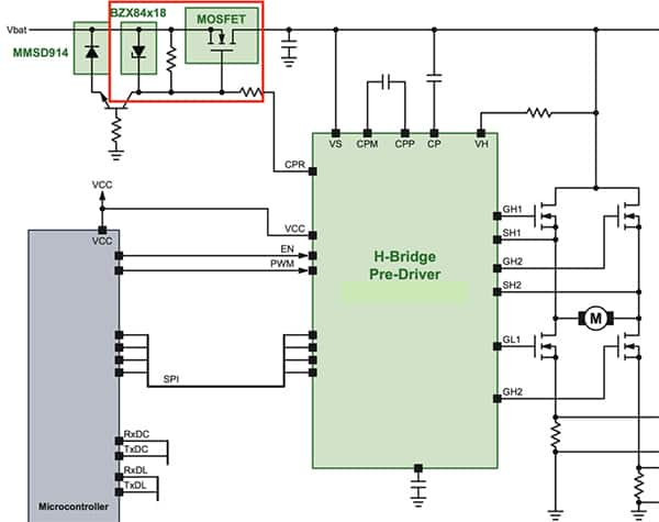
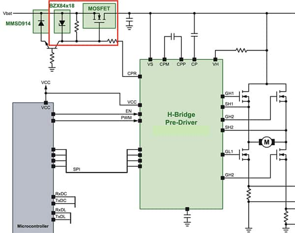
Figure 10: A portion of the door electronics BCU shows a linear regulator (highlighted) assembled from discrete components. This device regulates the car battery voltage (Vbat) to the supply voltage (VS) required by the actuator bridge. (Image source: ON Semiconductor)
A suitable Zener diode for this application is the SZBZX84C5V1LT3G from ON Semiconductor. This is an automotive (AEC-Q101) grade Zener diode available in a compact SOT-23 package. These devices provide voltage regulation with minimal space requirements. The Zener diode has a maximum power dissipation of 250 mW and a Zener breakdown voltage capability ranging from 2.4 to 75 V, depending on the components selected.
The complete regulator requires a resistor to limit the current flowing through the Zener diode. The resistor should be chosen to allow enough current to flow to the load and the Zener for regulation, but not too much. This Zener regulator has a high source impedance because all the load current must flow through the current limiting resistor, limiting the amount of current the regulator can provide to the load. This limitation can be overcome by buffering the output of the Zener diode with a source follower, such as the MOSFET shown in Figure 10.
Conclusion
Door electronics are becoming more complex as automakers add more features to vehicles. This trend makes it more difficult for engineers to design systems that meet stringent cost, weight, space and reliability constraints.
As mentioned above, ASIC, ASSP and discrete components designed to meet automotive standards can complement each other, thereby alleviating design challenges and allowing a modular approach to door electronics system design. Such an approach makes it easier to meet specifications and BOM constraints while maintaining excellent performance and reliability.

