Common photoelectric signal chains and selection references
Photodiodes, whose internal structure is a semiconductor device composed of a PN junction. Like common diodes, they have the characteristic of unidirectional conduction. Applications such as color measurement, emission spectrometers, gas detectors, and turbidity meters usually use photodiodes to achieve precision optical measurements.
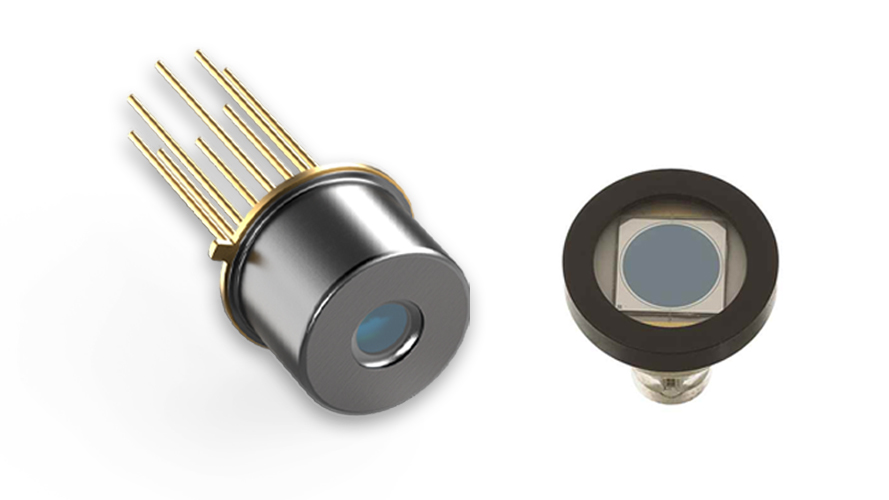
Figure 1 Photodiode appearance
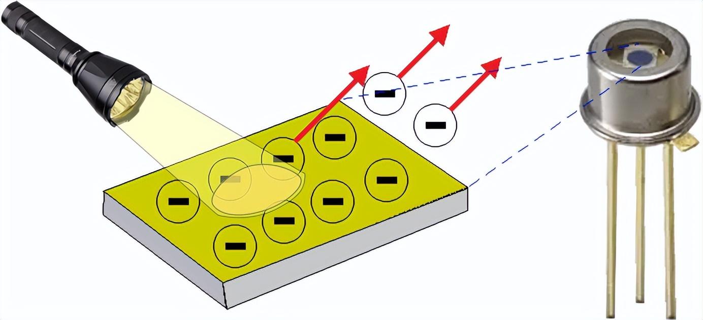
Figure 2 Photodiode internal structure
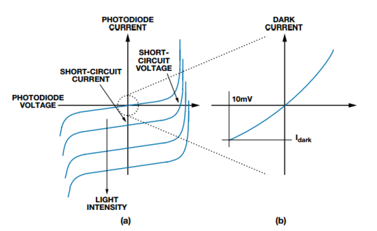
Figure 3 Typical photodiode transfer function characteristic diagram
I. Photodiode working mode
The basic principle of photodiodes is: by absorbing light energy and converting it into electrical signals when it is irradiated to the P-N junction. There are two common working modes:
Photoconductive mode (reverse bias)
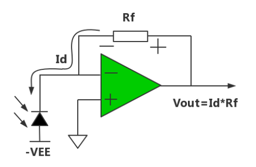
Figure 4 Reverse bias
Photovoltaic mode (zero bias)
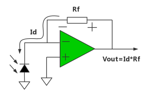
Figure 5 Zero bias
Characteristics of photoconductive mode:
● Fast response speed
● Large dark current
● Affects linearity
● Characteristics of photovoltaic mode:
● Small dark current
● Affects linearity
II. Common signal chain of photodiodes
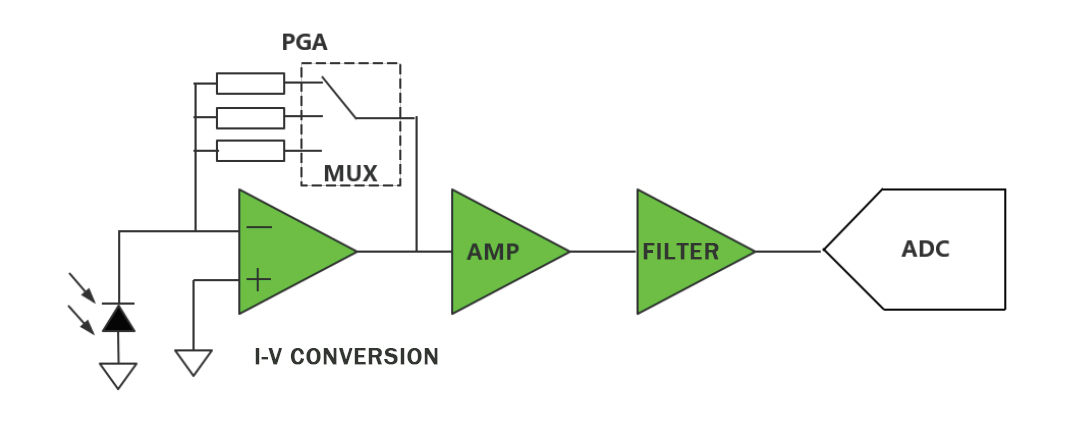
Figure 6 Principle of common signal chain
As shown in the figure above, the common signal chain is divided into four levels:
First-level signal chain:
I-V conversion, generally PGA is done in the first level, because the thermal noise and current noise of the resistor will appear directly at the output end. If PGA is done in the latter stage, the noise of the previous stage will be amplified, and the total noise will become larger.
Second-level signal chain:
Amplification, according to the specific signal requirements of the customer, can be omitted.
Third-level signal chain:
Filter, can be configured as low-pass, band-pass, high-pass, according to specific needs, the position can be adjusted to the second level.
Fourth-level signal chain:
ADC sampling, select the accuracy and type of ADC according to specific needs.
III. Photodiode synchronous detection signal chain
Figure 7 Principle of synchronous detection signal chain
The synchronous detection method adds DC isolation and analog switches to the signal chain to flip the signal. The final output DC signal is AD sampled, which can reduce the dynamic characteristics of the ADC, but the overall link will be much more complicated. The specific selection depends on customer needs.
IV. I-V conversion amplifier selection
I-V conversion is the most important in the entire signal chain. Whether the selection is appropriate will affect the performance of the entire signal chain. Because the photodiode output is a current signal, the amplifier should be a FET type with better current characteristics.
The indicators that need to be paid attention to are as follows:
● Offset current
● Bias current
● Offset voltage
● Bandwidth and slew rate
● Noise and temperature drift
The selection of each indicator should be based on the actual application of the customer.
For example: the output current range of the photodiode of this system is 1nA~1uA, and the system accuracy must reach 1%. Then our circuit selection index must basically reach the level of one thousandth, so that the accumulated errors of each level plus other errors can ensure that the accuracy of the entire system can reach the level of 1%. The minimum output of the photodiode is 1nA, so the offset current and bias current must basically reach 1nA/1000=1pA. The offset voltage should be selected according to the bias voltage requirements of the photodiode, which can generally meet the requirements. The bandwidth and slew rate should be selected according to the bandwidth of the signal. The smaller the noise and temperature drift, the better, but the price will also be higher.
Ⅴ. Device selection intermediate stage op amp and ADC
Intermediate stage op amp
The signal has been amplified by the pre-stage and has a good signal-to-noise ratio. The requirements for the intermediate stage op amp are not very high. When selecting, pay attention to the power supply range, bandwidth slew rate, input and output range. Generally, the problem is not very big, so I will not list and explain the specific models recommended here.
ADC
There are many choices for ADC. Generally, a 16-bit SAR ADC is enough. If the customer's system accuracy requirements are very high, but the signal frequency is not high, a high-bit ∑-△ type can be selected. The selection should pay attention to sampling speed, power supply range, input range, gain error, INL, DNL, etc.
VI. Summary
The application described in this article is to help circuit designers face common optoelectronic signal chains and selection references. At the same time, the basic signal conditioning circuits and principles are introduced in detail, and the complete device selection recommendations and features are listed. The correct selection of devices helps to increase the dynamic range and suppress noise.
